


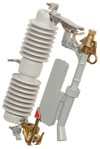
Fault Tamer® Fuse Limiter
For outdoor distribution, 15 kV through 25 kV
Combines the functionality of a conventional fuse cutout and a backup current-limiting fuse in one powerful, easy-to-install package
S&C Fault Tamer combines the functionality of a conventional fuse cutout and a backup current-limiting fuse in one powerful, easy-to-install package for the protection of new or existing overhead pole-top transformers through 25 kV. Fault Tamer addresses the critical issues facing protection engineers today.
Fault Tamer is manufactured in accordance with a quality system certified to ISO9001:2000.
Fault Tamer provides these features and benefits over traditional fuse cutouts, or cutouts used in combination with backup current-limiting fuses.
Improved Transformer Protection
- Ideally suited for protecting single- or three-phase transformers through
- 100 kVA single-phase at 15 kV
- 167 kVA single-phase at 25 kV
- Excellent continuous, hot-load pickup, and cold-load pickup capabilities.
- High surge withstand capability. Allows arrester to be mounted on transformer tank without increasing the chance of nuisance operations due to lightning.
Energy Limitation
- Minimizes equipment damage
- Reduces chances of catastrophic transformer failure from internal high-current faults.
- Minimizes bushing and tank damage due to external primary faults.
- Improves service continuity
- Provides complete coordination with upstream lateral fuses.
- Provides complete coordination with substation instantaneous relay settings.
- Enhances power quality
- Minimizes voltage dips that can cause sensitive electronic equipment to shut down.
Operational Characteristics
- Dropout action.
- No parts expelled during circuit interruption.
- Complies with Australian Spark Production Standard AS 1033.1-1990. Ideal for installation in areas prone to grass fires.
Handling Characteristics
- Easy to install/remove using extendo stick. No climbing or bucket truck needed to re-fuse . . . unlike conventional backup current-limiting fuses.
- Retrofits into all vintages of S&C Type XS Fuse Cutouts.
- Operable with Loadbuster®, S&C’s Portable Loadbreak Tool.
(On mobile, swipe left for remaining ratings information.)
| 50/60-Hz Ratings | |||||||
|---|---|---|---|---|---|---|---|
| Voltage, kV | Amperes, RMS | ||||||
| System Class, ANSI (IEC) |
System Maximum | BIL | Cont. | Interr., Sym. | |||
| 60 Hz | 50 Hz | ||||||
| Three- Phase♠ |
Phase-to- Neutral |
Three- Phase♠ |
Phase-to- Neutral |
||||
| 15 (12) | 15 | 8.7 | 15 | 8.7 | 110 | 20 | 12 000 |
| 15 (12) | 15 | 8.7 | 15 | 8.7 | 125 | 20 | 12 000 |
| 25 (24) | 29 | 16.8 | 26 | 15.1 | 125 | 20 | 12 000 |
| 25 (24) | 29 | 16.8 | 26 | 15.1 | 150 | 20 | 12 000 |
| 25 (24) | 29 | 16.8 | 26 | 15.1 | 150 | 20 | 12 000 |
♠ Also applies to phase-to-phase applications. Applications involving single-phase transformers connected phase-to-phase, as well as three-phase applications require the use of a Fault Tamer in each lead.
Fault Interruption — How It Works

On low magnitude faults, just the inexpensive fuse cartridge operates — similar to a conventional fuse cutout. Fault Tamer drops open, providing visual indication that it has operated.
On high-magnitude faults, both the fuse cartridge and the backup limiter operate. The fusible element in the limiter melts in multiple locations, creating myriad series arcs that promote an initial rapid increase in arc voltage. The increased arc voltage efficiently limits current to a small fraction of the prospective peak current. Fault current is driven to zero in a controlled fashion, as the fusible element burns back and arc energy is absorbed by the surrounding sand.
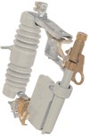
98021-D, 15 kV, 110 kV BIL
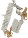
98072-D, 15 kV, 125 kV BIL
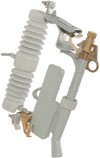
98022-D, 25 kV, 125 kV BIL
98052-D, 25 kV, 150 kV BIL
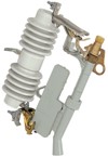
98053-D, 25 kV, 150 kV BIL
| Curve Type | Ampere Ratings | Fuse Type | TCC Number | Excel | |
|---|---|---|---|---|---|
| Minimum Melting | 3, 5, 7, 10, 15, 20 | Fault Tamer | TCC Number 450-8 | EXCEL | |
| Total Clearing | 3, 5, 7, 10, 15, 20 | Fault Tamer | TCC Number 450-8-3 | EXCEL |
| Curve Type | Ampere Ratings | Fuse Type | TCC Number | Excel | |
|---|---|---|---|---|---|
| Minimum Melting | 1, 2, 3, 5, 7, 10, 15, 20 | Fault Tamer | TCC Number 123-8 | EXCEL | |
| Total Clearing | 1, 2, 3, 5, 7, 10, 15, 20 | Fault Tamer | TCC Number 123-8-3 | EXCEL |


